|
|
|
This is an interesting input by Joe DeMarco, well-known for his contributions on the subject of geometrical applications in aviation art. For his analysis on the subject of ellipses and propellers you may wish to trawl down to the final part of this article("In additon to the foregoing....."). Here he independently demonstrates with typical skill the inherent risks from simplistically applying a preconceived and abstract figure to concrete situations in the real world. His succinct diagrams ably complement my words. The emphasis on the 3-point perspective is particularly relevant for our aerial depictions. Ron W -------------------------------------------------------
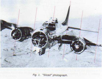
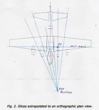
Extrapolating a Projection from a Photograph A month or two ago I tried to extrapolate the camera-to-aircraft viewing distance of a B17 from a photograph. It didn’t work too well because of the lack of sufficient details and check points. The idea was to make vertical “slices” through the airplane then transfer them to a 3-view. Later, Ron sent a photo titled “B17 Tail Chase” that lent itself very well to that process, and more. The photo, with six slices, is shown in Fig. 1. (More recently [Aug 29] Charles showed a similar diagram relative to telephoto lenses. Both processes are essentially the same but the following is a practical demonstration.) The plan is to translate the slices from the photograph into convergent lines on an orthographic image of the aircraft from which pertinent data may be inferred. A plan view suitable for the purpose was generated from Ron’s APM plot of the B17. The starting point in this exercise is easy; the No. 2 engine is seen almost head-on in the photograph, so it’s logical that the CV lies on that vertical slice. Another good candidate line is the one through the rudderpost. Transferring those two lines to the plan view produced a tentative EP at the point where they intersect. Other slices on the photograph are at the tips of the horizontal tail, the centerline of the turret, and the cowl opening and aft end of No. 3 engine. When all the slices have been lightly drawn in it’s then a matter of fine-tuning them to convergence into an EP, Fig. 2. One can expect reasonable, but not 100% accuracy from the process. Not only does much depend on the qualities of the photograph, but also on one’s judgment. Q: Where does the slice from the port stabilizer tip pass through the wing leading edge? A: It’s about 54% of the distance – scalable from the photograph – between engines nacelles 1 and 2, visible in the photo. The scale of the B17 plan is 1 in. = 6 ft., so the following parameter data was picked up from the plan view of the layout:
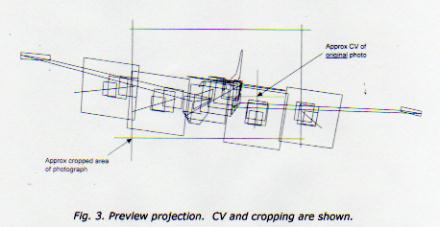
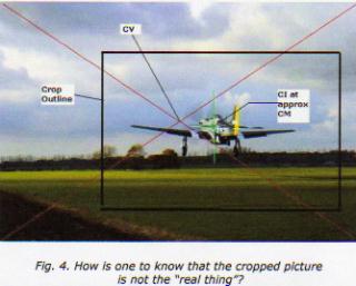
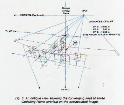
All things considered, and from the clues available, it should not be asking too much of one’s credibility to accept that the viewing parameters are “in the ballpark” and that the viewing distance is within ± 6 feet of the original camera location. Just as a matter of passing interest, the photograph was shot with a wide-angle lens. If it’s assumed that the image was distributed equally to the right and left of the CV, the right edge must have been out near the end of the port wing. The right side of the picture was severely cropped to enhance the presentation. Lack of awareness of those qualities might lead many to the mistaken belief that the CV is at the intersection of diagonals from the corners of the print. A similar example is shown in Fig. 4. If one had not seen the original print, one could easily assume that the cropped portion is the original. (Hmm…I have no way of knowing that the larger picture itself is the original!)
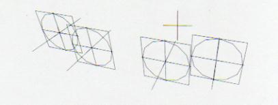
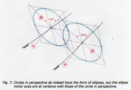
In addition to the foregoing, the Fig. 1 photo presents an excellent opportunity to demonstrate once again that the M/m axes of propeller disks – when seen as ellipses – seldom align with the propeller “axles”. (A word to the unconvinced: Note that the following illustrations are derived from a photograph (Fig. 1), not from a “contrived” geometric projection.) In Fig. 6 the prop squares have been separated from the background clutter and filled in with 12-segment APM circles. “Points” on the circles make it obvious that the points of tangency and the vertical and horizontal axes coincide with the geometric centers of the square’s sides. Also, the circles’ centers are now seen as the third axis – the longitudinal “axle”. The figure illustrates other features of “circles in perspective”: the squares sides are no longer parallel; the circle/square axes are no longer at right angles; and although the circles’ centers are at the intersection of diagonals from the square’s corners, halves of the circles are not symmetrical. In a typical example of circles-in-perspective-are-not-ellipses, the circles for prop disks #4 and #3 are intuited around the previously calculated APM segmented circles in Fig. 7. It is quite obvious – but entirely incidental – that circles in perspective have the characteristic shape of ellipses. It is equally obvious that the ellipse axes are not in harmony with the axes (axles) of the circles in perspective. Also easily discernible in Fig. 7 is: the Major (M) and minor (m) axes of the ellipses are at right angles, the halves of each ellipse are symmetrical, and, due to “perspective”, the ellipse geometric centers are offset from the circles geometric centers. (The geometric center of the ellipse is easily found by measuring; the Major and minor (M/m) axes of the ellipse can be determined with the aid of a compass and triangle.) SJD 9/9/06
For the benefit of anyone not familiar with it, Ron Wong’s much maligned and ridiculed pro circle-in-perspective-not-an-ellipse stance is appended below. It’s somewhat abstruse but I agree with its principal. [Ellipses] are a class of symmetric geometric figures which may be derived in a number of simple ways: by rotating a fixed loop about a pair of foci; from a mathematical conic section; or by viewing a circular shape obliquely. By virtue of its continuous outline, a circle compensates for the common effects of perspective and appears to maintain its symmetry when viewed at an angle, so giving the outward appearance of a constant ellipse. The illusion is quickly dispelled when linear perspective is applied to plot a circular shape inside its square, and locate its centre by intersecting diagonals. Then, proceed to locate its centre as a symmetrical "ellipse", which is at the intersection of its longest and shortest axes. The two centres do not coincide. In other words, a circular shape, seen in perspective as a solid form rather than an abstract outline, is not really an ellipse, for the obvious reason that the near half of the shape is larger than the far half, so that its centre is eccentric to its outline. It is an ellipse only figuratively speaking…the greater the amount of perspective (foreshortening), the greater will be the corresponding displacement and distortion. From: “Controversies & Caveats”, by Ronald Wong. |